- 您现在的位置:买卖IC网 > Sheet目录337 > LT3466EDD#PBF (Linear Technology)IC LED DRIVR WHITE BCKLGT 10-DFN
LT3466
APPLICATIO S I FOR ATIO
D =
DUTY CYCLE
The duty cycle for a step-up converter is given by:
V OUT + V D – V IN
V OUT + V D – V CESAT
where:
V OUT = Output voltage
V D = Schottky forward voltage drop
V CESAT = Saturation voltage of the switch
V IN = Input battery voltage
The maximum duty cycle achievable for LT3466 is 96%
(typ) when running at 1MHz switching frequency. It in-
creases to 99% (typ) when run at 200kHz and drops to
92% (typ) at 2MHz. Always ensure that the converter is not
duty-cycle limited when powering the LEDs at a given
switching frequency.
SETTING THE SWITCHING FREQUENCY
The LT3466 uses a constant frequency architecture that
can be programmed over a 200KHz to 2MHz range with a
single external timing resistor from the R T pin to ground.
The nominal voltage on the R T pin is 0.54V, and the
current that flows into the timing resistor is used to
charge and discharge an internal oscillator capacitor. A
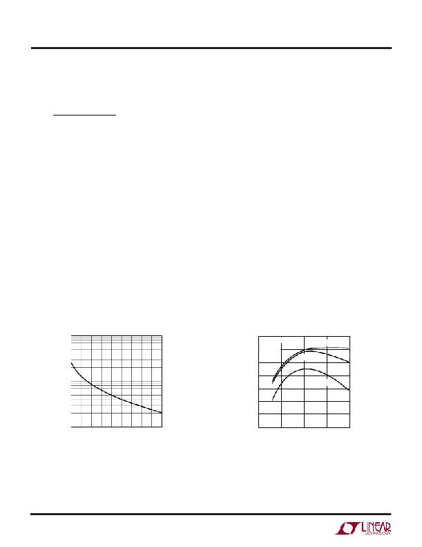
graph for selecting the value of R T for a given operating
frequency is shown in Figure 6.
OPERATING FREQUENCY SELECTION
The choice of operating frequency is determined by sev-
eral factors. There is a tradeoff between efficiency and
component size. Higher switching frequency allows the
use of smaller inductors albeit at the cost of increased
switching losses and decreased efficiency.
Another consideration is the maximum duty cycle achiev-
able. In certain applications, the converter needs to oper-
ate at the maximum duty cycle in order to light up the
maximum number of LEDs. The LT3466 has a fixed
oscillator off-time and a variable on-time. As a result, the
maximum duty cycle increases as the switching frequency
is decreased.
The circuit of Figure 1 is operated with different values of
timing resistor (R T ). R T is chosen so as to run the
converters at 800kHz (R T = 63.4k), 1.25MHz (R T = 39.1k)
and 2MHz (R T = 20.5k). The efficiency comparison for
different R T values is shown in Figure 7.
1000
85
CIRCUIT OF FIGURE 1
V IN = 3.6V
80 8/8 LEDs
R T = 63.4k
R T = 39.1k
75
70
100
65
60
55
R T = 20.5k
10
200
600
1000
1400
1800
50
0
5
10
15
20
OSCILLATOR FREQUENCY (kHz)
3466 F06
Figure 6. Timing Resistor (R T ) Value
LED CURRENT (mA)
3466 F07
Figure 7. Efficiency Comparison for Different R T Resistors
3466fa
10
发布紧急采购,3分钟左右您将得到回复。
相关PDF资料
LT3474IFE#PBF
IC LED DRVR HP CONS CURR 16TSSOP
LT3475EFE-1#PBF
IC LED DRVR HP CONS CURR 20TSSOP
LT3476EUHF#PBF
IC LED DRVR HP CONST CURR 38-QFN
LT3477EFE#PBF
IC LED DRVR HP CONS CURR 20TSSOP
LT3478IFE#PBF
IC LED DRVR HP CONS CURR 16TSSOP
LT3486EFE#PBF
IC LED DRVR WHITE BCKLGT 16TSSOP
LT3491EDC#TRMPBF
IC LED DRIVER WHITE BCKLGT 6-DFN
LT3492IFE#TRPBF
IC LED DVR HP CONST CURR 28TSSOP
相关代理商/技术参数
LT3466EDD#PBF
制造商:Linear Technology 功能描述:LED DRIVER BOOST PWM 1MHZ 制造商:Linear Technology 功能描述:LED DRIVER, BOOST, PWM, 1MHZ, DFN-10
LT3466EDD#TR
功能描述:IC LED DRIVR WHITE BCKLGT 10-DFN RoHS:否 类别:集成电路 (IC) >> PMIC - LED 驱动器 系列:- 标准包装:6,000 系列:- 恒定电流:- 恒定电压:- 拓扑:开路漏极,PWM 输出数:4 内部驱动器:是 类型 - 主要:LED 闪烁器 类型 - 次要:- 频率:400kHz 电源电压:2.3 V ~ 5.5 V 输出电压:- 安装类型:表面贴装 封装/外壳:8-VFDFN 裸露焊盘 供应商设备封装:8-HVSON 包装:带卷 (TR) 工作温度:-40°C ~ 85°C 其它名称:935286881118PCA9553TK/02-TPCA9553TK/02-T-ND
LT3466EDD#TRPBF
功能描述:IC LED DRIVR WHITE BCKLGT 10-DFN RoHS:是 类别:集成电路 (IC) >> PMIC - LED 驱动器 系列:- 标准包装:6,000 系列:- 恒定电流:- 恒定电压:- 拓扑:开路漏极,PWM 输出数:4 内部驱动器:是 类型 - 主要:LED 闪烁器 类型 - 次要:- 频率:400kHz 电源电压:2.3 V ~ 5.5 V 输出电压:- 安装类型:表面贴装 封装/外壳:8-VFDFN 裸露焊盘 供应商设备封装:8-HVSON 包装:带卷 (TR) 工作温度:-40°C ~ 85°C 其它名称:935286881118PCA9553TK/02-TPCA9553TK/02-T-ND
LT3466EDD-1
制造商:Linear Technology 功能描述:LED DRVR 10Segment 3.3V/5V/9V/12V/15V/18V 10-Pin DFN EP
LT3466EDD-1#PBF
功能描述:IC LED DRIVR WHITE BCKLGT 10-DFN RoHS:是 类别:集成电路 (IC) >> PMIC - LED 驱动器 系列:- 标准包装:60 系列:- 恒定电流:- 恒定电压:- 拓扑:线性(LDO),PWM,升压(升压) 输出数:8 内部驱动器:是 类型 - 主要:背光 类型 - 次要:RGB,白色 LED 频率:500kHz ~ 1.5MHz 电源电压:4.75 V ~ 26 V 输出电压:45V 安装类型:* 封装/外壳:* 供应商设备封装:* 包装:* 工作温度:-40°C ~ 85°C
LT3466EDD-1#PBF
制造商:Linear Technology 功能描述:IC, LED DRVR, DFN10
LT3466EDD-1#TRPBF
功能描述:IC LED DRIVR WHITE BCKLGT 10-DFN RoHS:是 类别:集成电路 (IC) >> PMIC - LED 驱动器 系列:- 标准包装:6,000 系列:- 恒定电流:- 恒定电压:- 拓扑:开路漏极,PWM 输出数:4 内部驱动器:是 类型 - 主要:LED 闪烁器 类型 - 次要:- 频率:400kHz 电源电压:2.3 V ~ 5.5 V 输出电压:- 安装类型:表面贴装 封装/外壳:8-VFDFN 裸露焊盘 供应商设备封装:8-HVSON 包装:带卷 (TR) 工作温度:-40°C ~ 85°C 其它名称:935286881118PCA9553TK/02-TPCA9553TK/02-T-ND
LT3466EDDPBF
制造商:Linear Technology 功能描述:Dual Full Func White LED contrlr,LT3466
